13 KiB
Playzing Builder's Manual
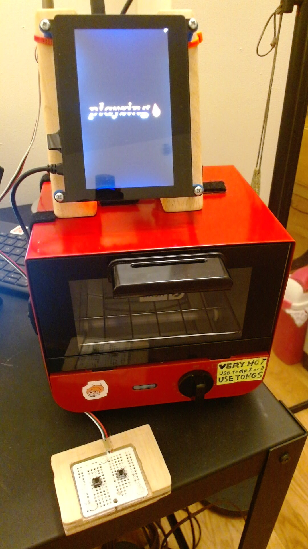
The Playzing contains three independent parts: a Raspberry Pi portable gaming device, a small toaster oven, and a custom built gamepad. Each part can run on its own, but like the Megazord, its combination is greater than the sum of its parts. When assembled into a single unit, these three components become the Playzing, an interactive social cooking experience that brings together people, food, and digital games.
This manual explains step-by-step how to use a list of supplies to build the Playzing hardware and how to install the software.
License
The code is released under the zlib license. The documentation, including this manual, is released under CC BY 4.0. See LICENSE.md for details.
Supplies
- Raspberry Pi 3B+
- 4MB+ micro SD card
- Eviciv 5" 800×480 LCD Screen
- DASH Mini Toaster Oven
- 2 × Triangle wood blocks
- 2 × Buttons
- 2x1.5" Prototype breadboard
- 1.5'+ 3-pin JST cable
- Small piece of wood (3 x 2-1/4 x 3/4" recommended, but any size that fits the breadboard is fine)
- Grill gasket tape
- 4 × 1" Corner brace
- 4 × #6 1/2" Flat-head wood or sheet metal screws
- 6 × #6 1/2" Round-head wood or sheet metal screws
- 4 × 3/4" Spacers
- 4 × #6 1 1/4" Round-head wood screws
- 4 × 3/4" Flat-head machine screws and nuts
- USB keyboard
- Drill
Raspberry Pi
Before mounting anything, set up and test the Raspberry Pi with the screen and gamepad.
Operating system
Install Raspberry Pi Lite OS on a micro SD card with at least 4MB. Using Raspberry Pi Imager is recommended.
Screen
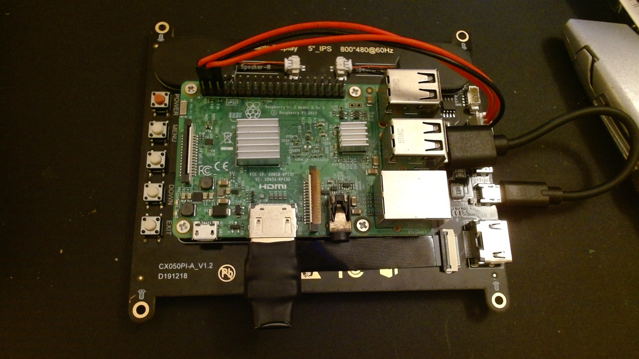
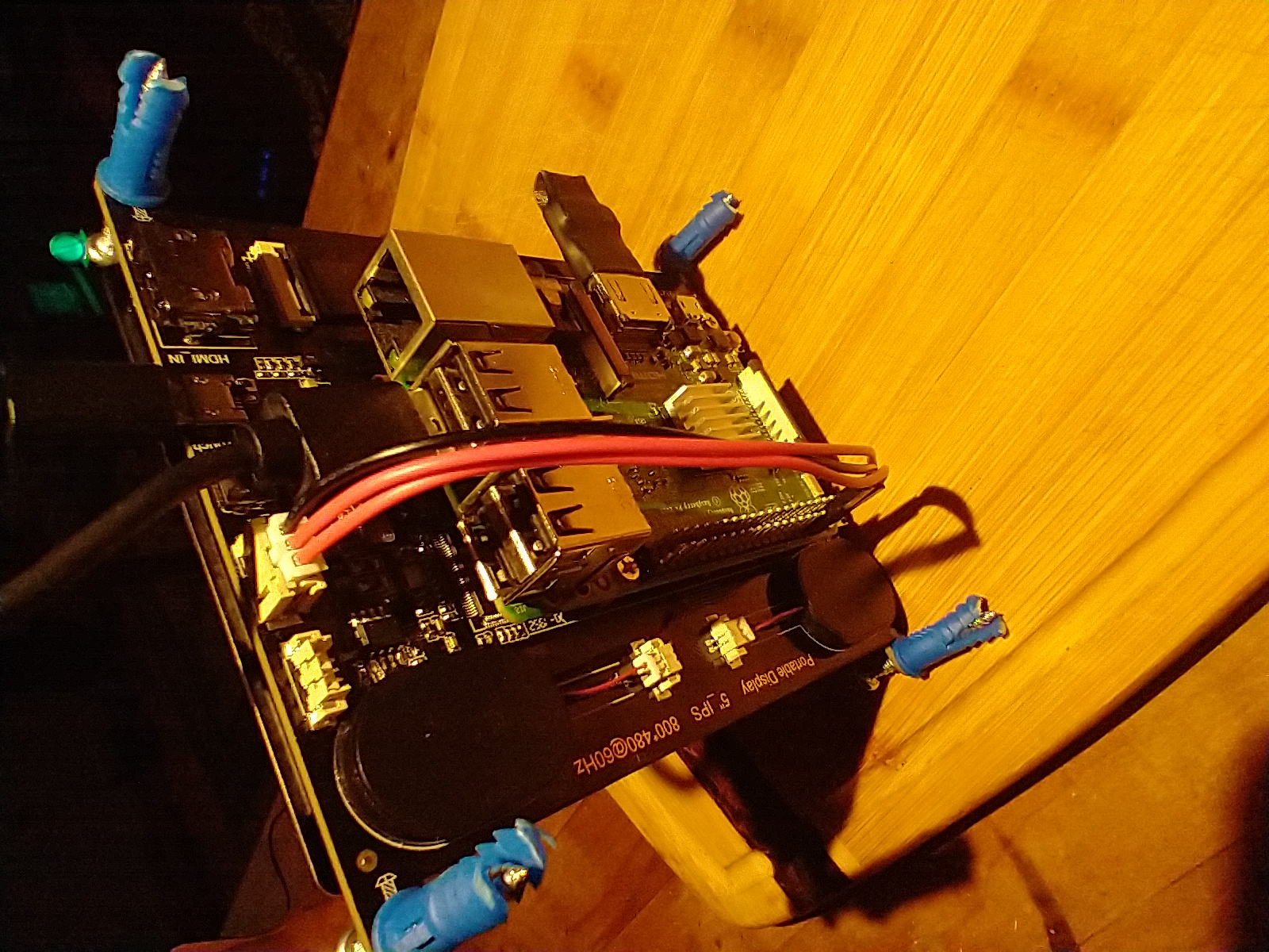
The Eviciv 5" LCD screen comes with detailed instructions for connecting the screen to a Raspberry Pi 3 or 4. It also comes with a custom ribbon cable for connecting HDMI and a custom jumper cable for connecting to power. Follow the instructions for setting up the screen with the custom cables, then use the supplied screws to mount the Raspberry Pi to the back of the screen.
First boot
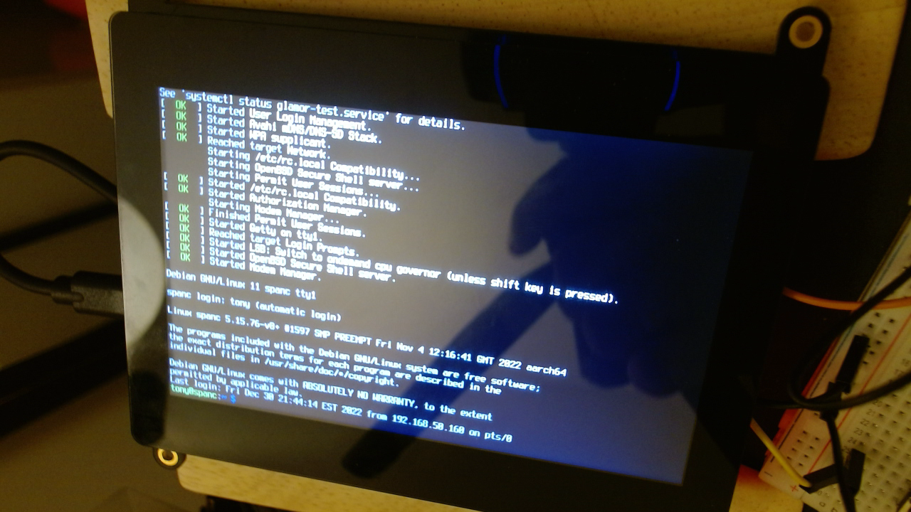
Connect a USB keyboard to the Raspberry Pi and plug it in to boot it. At the command line, run the configuration script.
sudo raspi-config
Disable the login prompt using System Options -> Boot / Auto Login -> Console Autologin.
Game
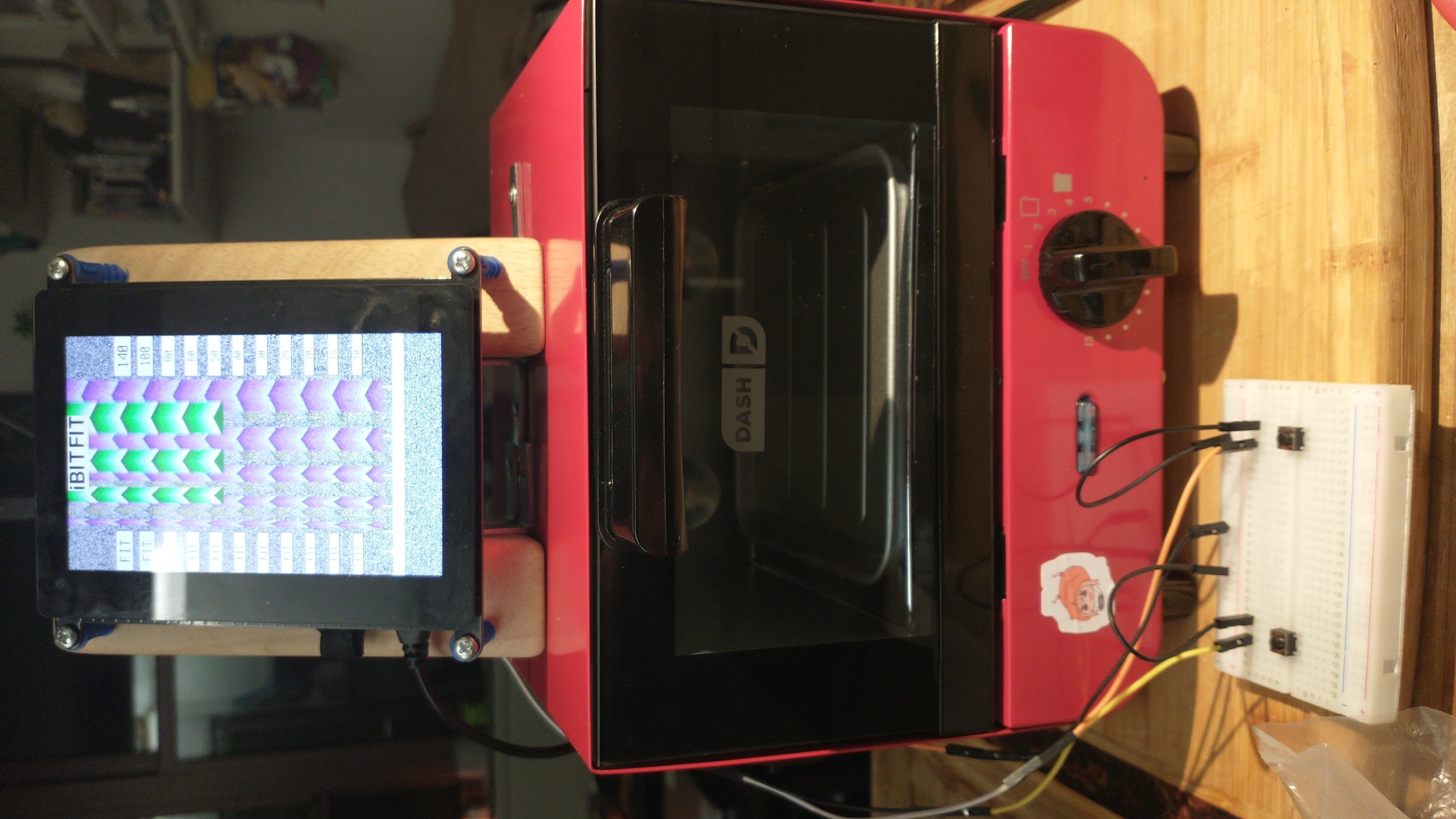
iBitFit is the first game compatible with the Playzing entertainment device and gamepad. It is able to run using the KMS video driver and can read gamepad input through the Raspberry Pi GPIO interface. It supports an option to rotate the display, which is necessary for the vertically oriented screen.
The Playzing repository has a game launcher in development which is able to display a title logo at boot and launch iBitFit on any key press. From the root of this repository, run the following commands to download iBitFit, then run the launcher.
cd games/
git clone https://open.shampoo.ooo/shampoo/ibitfit
cd ..
./Playzing.py --config ",display,rotated,yes"
Test the game using the left and right buttons on the USB keyboard.
Autorun
To start the game launcher automatically at system boot, create a file at /etc/systemd/system/playzing.service with the following contents. Substitute the correct user name for [USER].
[Unit]
Description=Game launcher for the Playzing entertainment device
After=multi-user.target

[Service]
ExecStart=/home/[USER]/playzing/Playzing --go-to-dir --config ",display,rotated,yes"
KillSignal=SIGINT
Restart=always
RestartSec=5s
TimeoutStartSec=5s

[Install]
WantedBy=default.target
and enable it
sudo systemctl enable playzing.service
Now the launcher will open at startup and will restart itself if it ever is closed or crashes, and it can be controlled through systemd
> sudo systemctl start playzing
...
> sudo systemctl stop playzing
Since it restarts automatically when quit with the usual quit button, there is also SHIFT + q to permanently quit and get back to the Raspberry Pi console.
Gamepad
After setting up the Raspberry Pi and screen, build and test the gamepad.
Buttons
Two buttons need to be connected to the Raspberry Pi's GPIO 24 and 23, and each also needs to connect to the Raspberry Pi's ground pin. In the software, the input pins are set to pull-up to create a high signal when the button is unpressed. When the button is pressed, it connects the input pin to the ground pin, and the signal is pulled low.
The buttons can be connected with a regular breadboard before being soldered into the prototype breadboard. The black wires in the photo are connected to ground (pin 20 on the Pi). The yellow wire is connected to GPIO 24 (also known as pin 18), and the orange wire is connected to GPIO 23 (also known as pin 16).
Gamepad circuit board
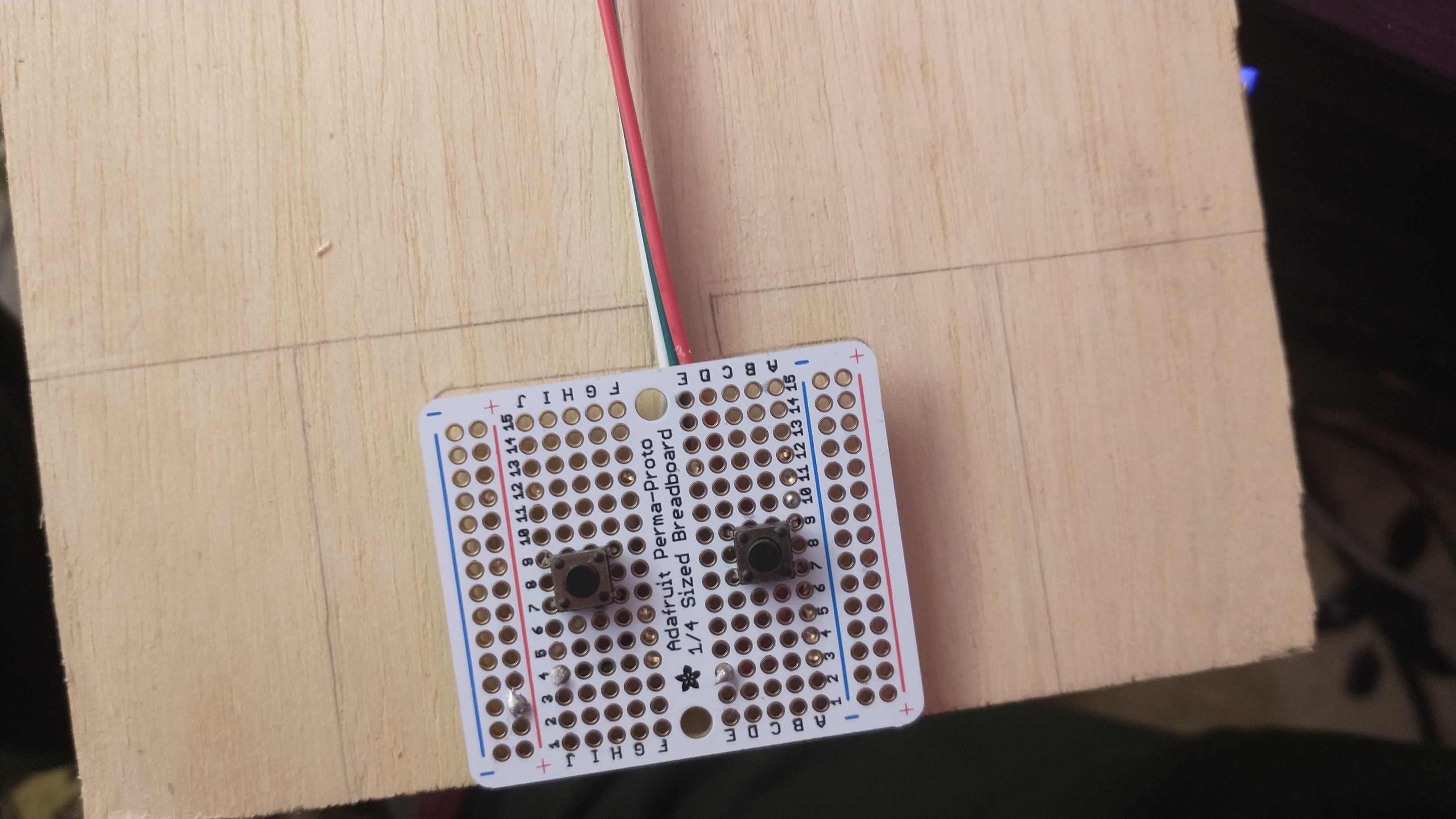
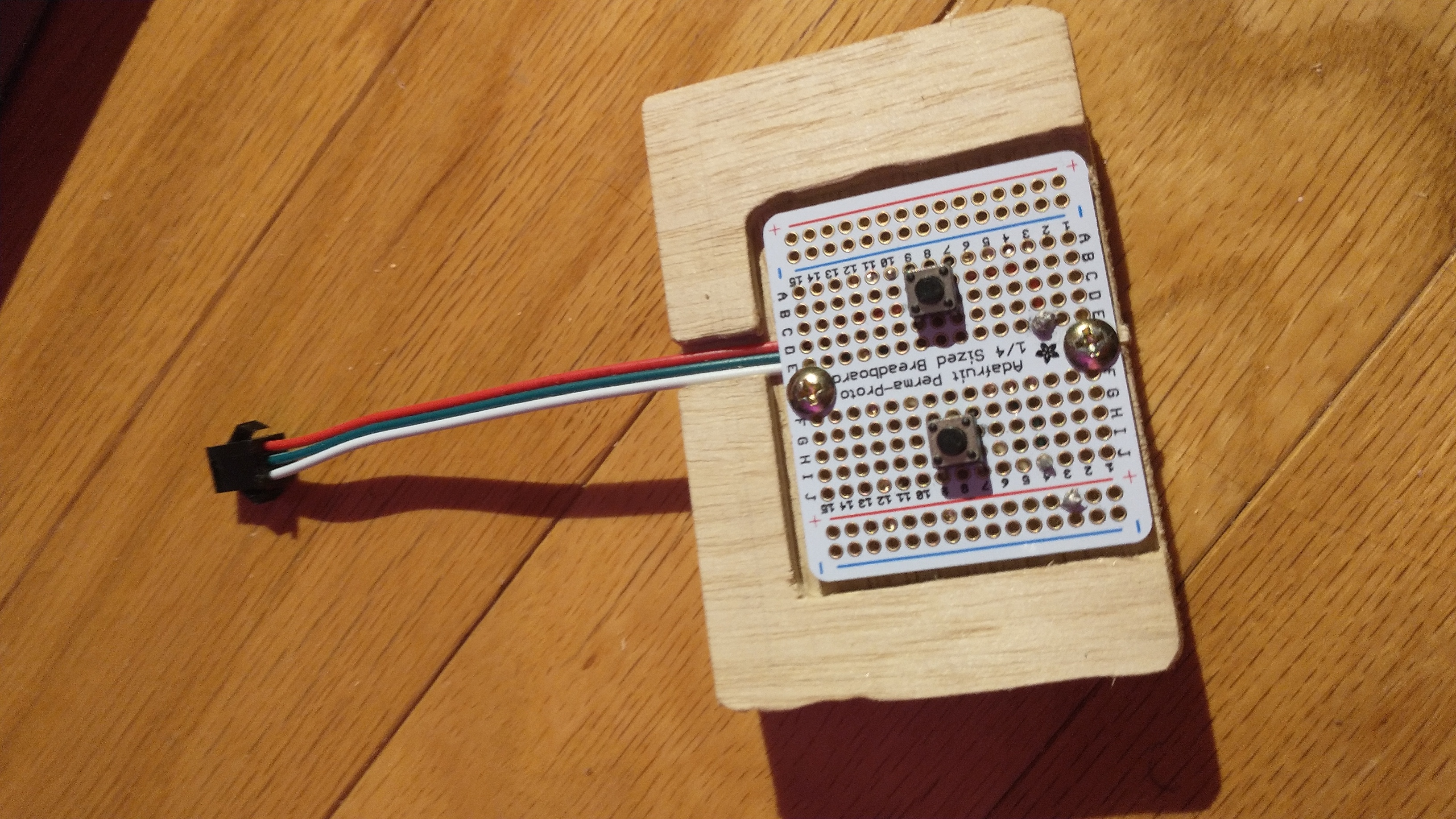
After testing the button circuit, solder it onto the prototype breadboard. The buttons should be centered vertically with a bit of horizontal space between them. Put them through the front of the breadboard, and solder each pin on the back.
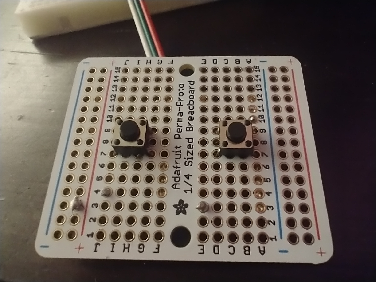
If using the same JST connector linked in the supplies, use the smaller section with exposed wires at one end to create the connection between the gamepad circuit and the Raspberry Pi. The other end of the smaller section can be plugged into the male end of the longer cable, which can then be plugged into the Raspberry Pi. Other types of connections are fine as long as one end can plug into the Raspberry Pi pin header.
The placement of the JST wires may depend on the breadboard, but it is recommended to connect each wire toward the bottom (closer to the player) so that the sheathed parts of the wires can lay flat against the underside and emerge from the top (closer to the device). If preferred, the wires can be shortened and re-stripped so they fit without bending, making them easier to solder. The wires should be inserted on the underside and soldered at the top of the board.
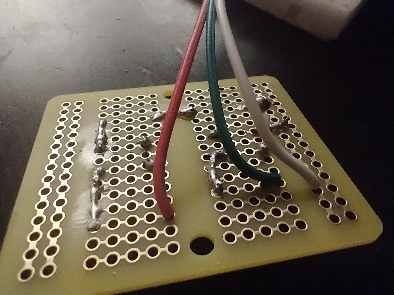
Once the wires are soldered, connect them to the buttons using solder to create bridges between the pin holes on the underside of the board. The exact connections will depend on the board, but the ground wire should connect to both buttons (using any of the button pins), the middle wire should connect to the left button, and the last wire should connect to right button, making sure not to directly connect ground to either of the GPIO pins. In the photo, the white wire is ground, the green wire is GPIO 24, and the red wire is GPIO 23.
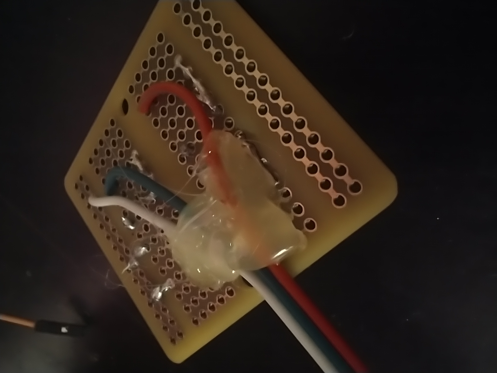
Hot glue the wires onto the underside of the board.
Attach the socket end of the three JST wires to the Raspberry Pi's GPIO pins 20, 18, and 16 (ground, GPIO 24, and GPIO 23). The gamepad buttons should be working to control iBitFit.
Screen mount
The mounting holes of the screen need to be widened slightly if using the #6 1-1/4" screws. Alternatively, it's possible that smaller screws can be used as long as they are long enough. To widen the screen's mounting holes, carefully drill a 7/64" drill bit into each hole.
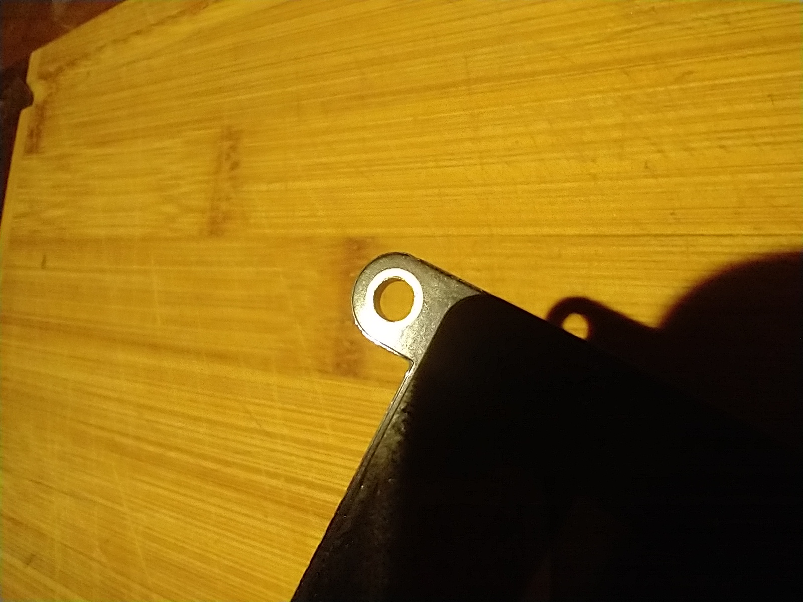
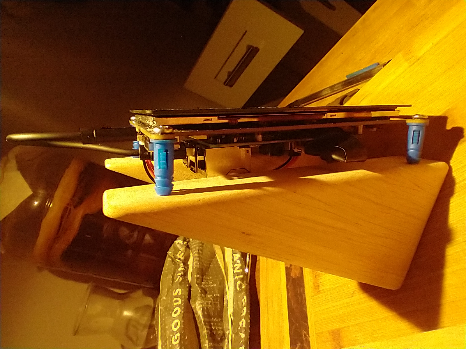
Put the screws through each hole and through the 3/4" spacers (in the photos, screw anchors are being used in place of the spacers).
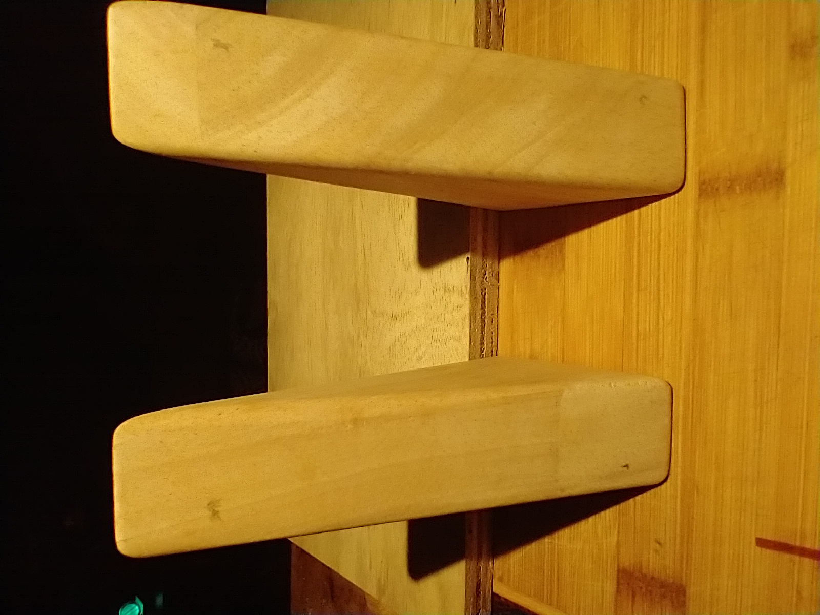
Stand the wood blocks up with 2 1/4" between them, using the shorter side as the base, and put their backs against a straight surface to keep them aligned. Use the screen and screws to mark where holes for the screws should be pre-drilled. Carefully hold the screen up to the blocks with the screws sticking out and the top screws 7/8" from the top of the blocks. Either carefully press the screws into the wood or mark with a pencil where to drill the holes.
Drill shallow holes for the screen screws into the wood block using a thin drill bit.
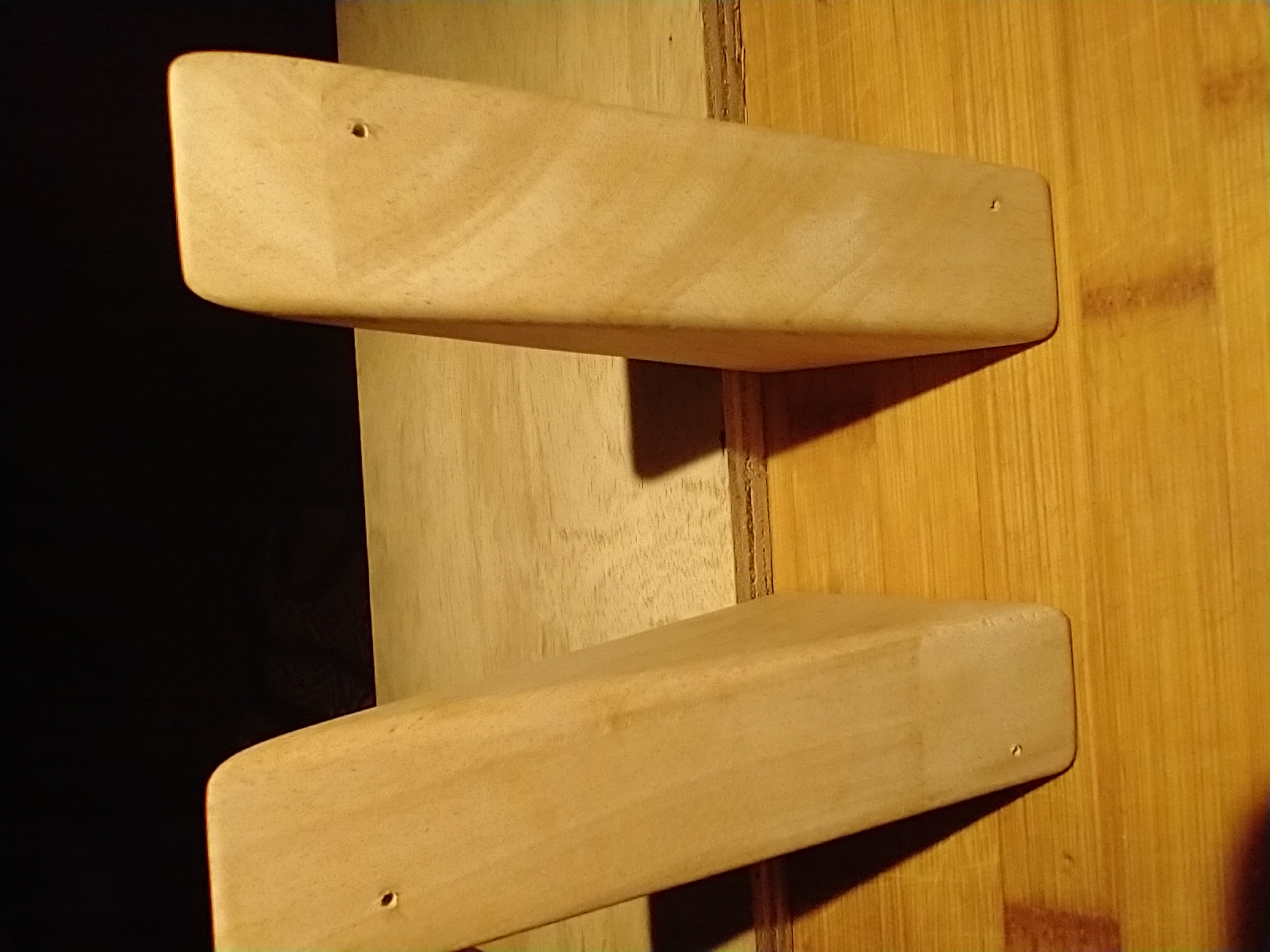
Drive the #6 1 1/4" screws through the spacers and into the wood blocks.
Because the roof of the oven has hollow sections on the left and right edges, only one bracket can go on the outside of the wood blocks. However, there will still be enough support to hold the wood in place with brackets on the inside and one on the outside. Place the brackets with one on the outer right side of the wood blocks, one on the inner right side, and two on the inner left side. Draw a mark with pencil where the screws will drill into the wood. Unscrew the screen from the blocks temporarily to create access for the drill and pre-drill holes into the wood using a thin drill bit. Drill the brackets in using 1/2" screws and reattach the screen.
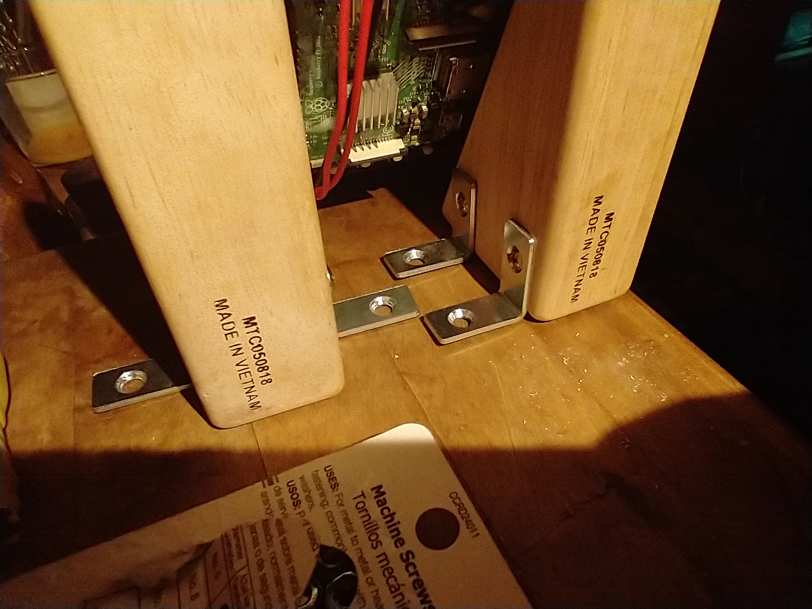
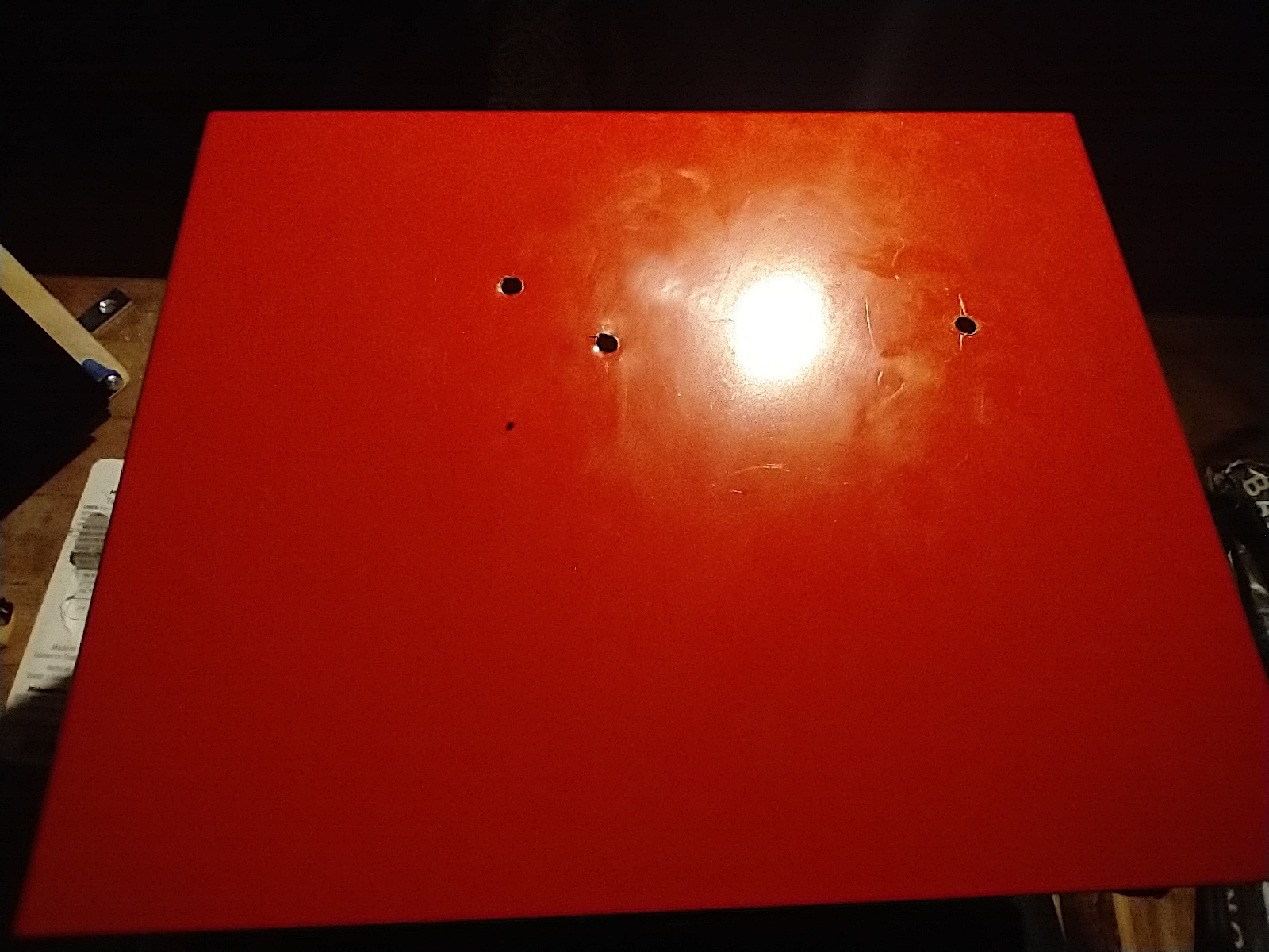
Place the entire mount on the roof of the oven and draw marks where the holes will be drilled into the roof for the brackets. The rightmost hole should be about 2 3/8" in from the top and 1 1/2" in from the right. The topmost hole should be about 2" in from the top and 3" in from the left. Drill holes through two layers of metal for the machine screws. Start with a thin bit and go up until the machine screws can be screwed into the holes. In the photos, there are only three holes because the lowest mark is above the oven's heating element, so I decided not to risk damaging the heating element with the drill. If drilled carefully, or the mount position is adjusted, it may be possible to drill all four holes safely.
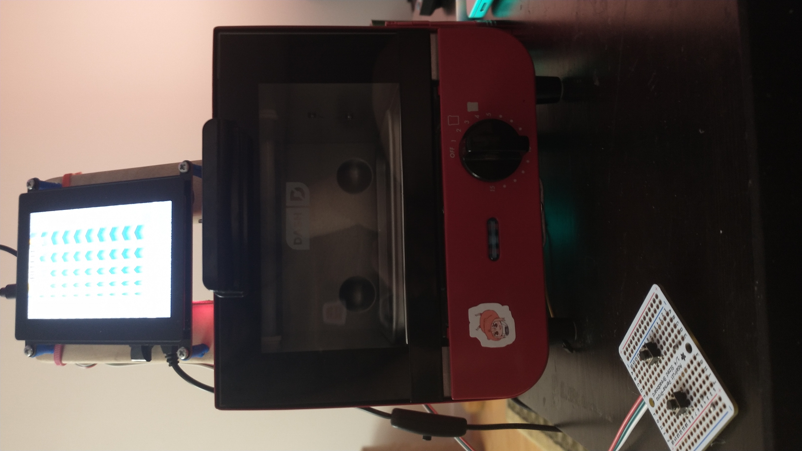
Screw the 3/4" machine screws in through the top and tighten the nut by hand on the other end by reaching under the ceiling of the oven. The display should be securely attached with the Raspberry Pi and gamepad working.
Gamepad shell
A piece of wood is used to create a shell for the gamepad. The suggested size 3 x 2-1/4 x 3/4" is a good portable size that fits well in the player's hands. However, any size is fine. It is recommended, but optional, to use a router to carve out an inset for the circuit board and attached wires in the middle of the bottom of the wood.
If using a router, trace along the gamepad circuit board where the wood will be carved. In this photo, there are extra marks where the entire wood block needed to be cut. Set the router depth to 1/8" and carve out the parts inside the outline.
Mount the circuit board to the wood by drilling 1/2" screws through the board's mount holes into the wood. If the board's holes are too small for the screws, widen the holes or drill new holes where there is no wiring.
Gasket tape
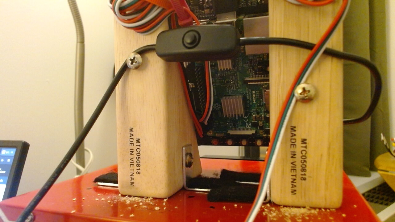
Because the surface of the oven can get very hot, it is important to keep the plastic wire sheathing of the gamepad and Raspberry Pi power supply wires from touching the metal. The gamepad and power wires can be run down the back of the oven along gasket tape to prevent them from touching the oven surface, and screws can be drilled for guiding the wire along the back of the wood blocks.
Find a good position for the power and gamepad wires, and drill two 1/2" screws into the back of the wood blocks to hold them in position.
Cut two long strips of gasket tape for protecting the power and gamepad cables. Cut four shorter strips to tape the wires to the backing gasket.
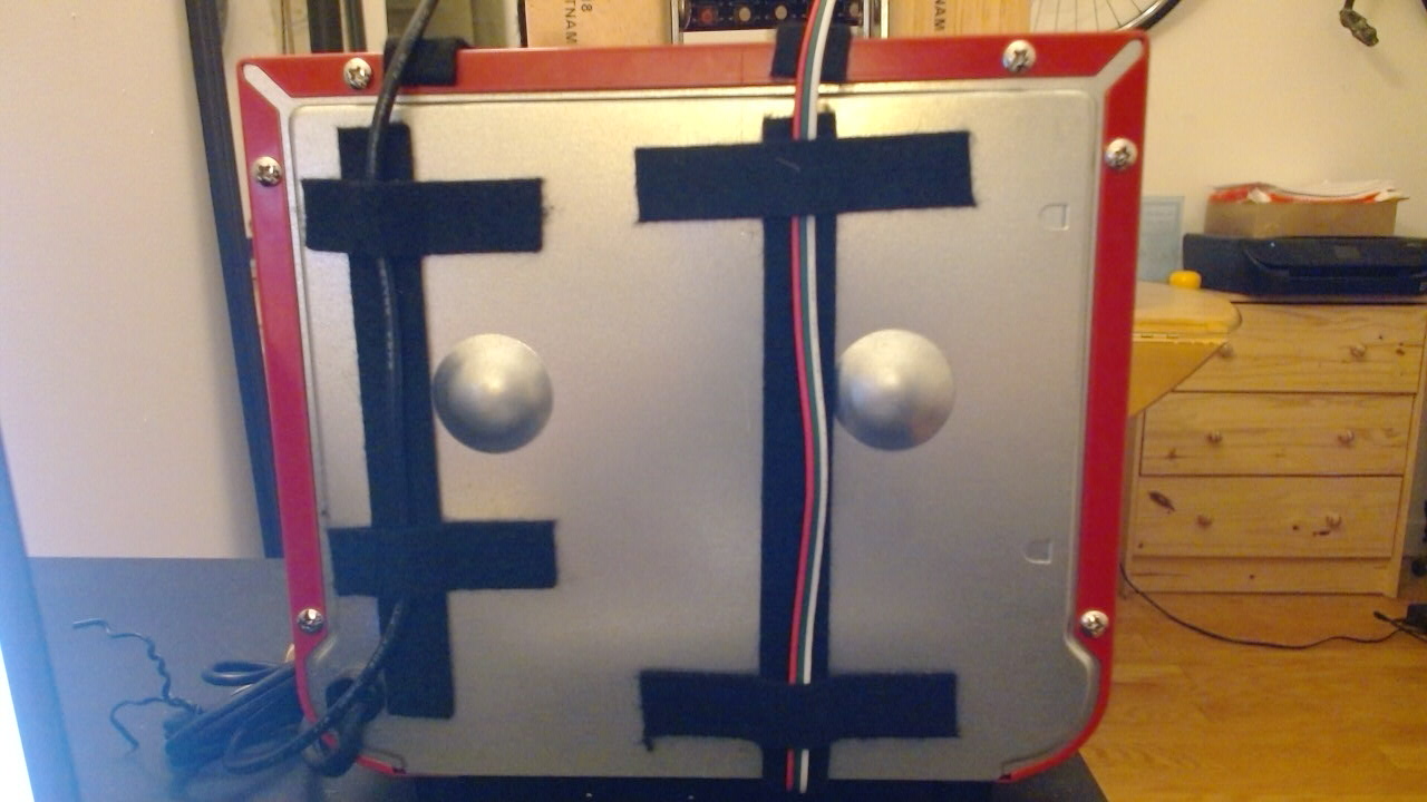
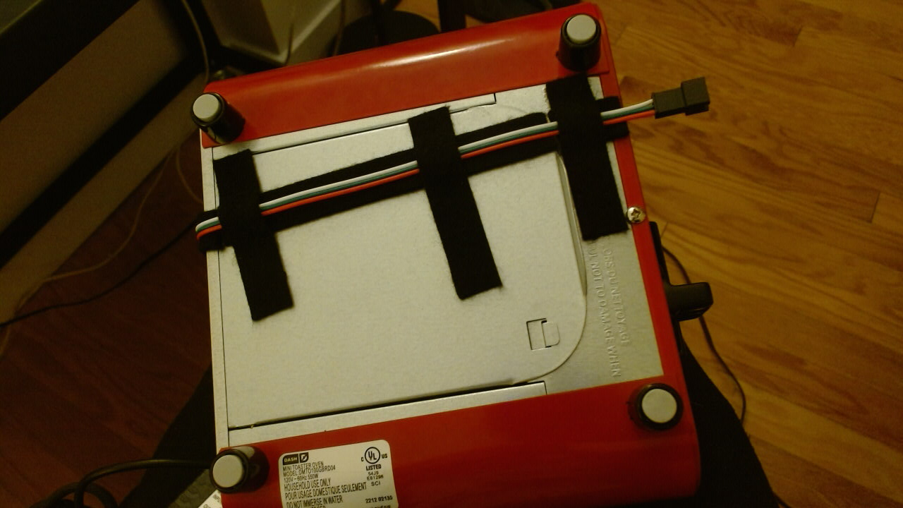
On the underside of the toaster, tape the gamepad wire to a long strip using three short strips. Cut the long strip where the bottom opens so the oven's bottom can still be opened and cleaned (though that will require re-taping the last short strip).
Let the games begin!