36 KiB
Scrapeboard Builder's Manual
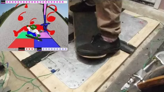
Scrapeboard is an alternative controller game that uses a skateboard deck and metal floor pads for input. In the game, the player is a lizard who is given a skatedeck by Tony Hawk and challenged to swords matches with a series of goons. The object of each match is to perform combinations of moves displayed on screen as quickly as possible.
The game is available to play at select game conventions and festivals, but it is also a D.I.Y. project that is not difficult to reproduce. This manual covers how to build a full Scrapeboard system. It includes how to install and test the software, how to build the electronics, and how to fabricate a controller using a skateboard deck, metal pads, and plywood.
Audience
It is intended for a general audience. There are steps that involve beginner level electronics and wood working. The instructions assume some understanding about how to connect components when using the Arduino. There are steps that require the use of a drill.
Purpose
The builder's manual was created so players could build Scrapeboard on their own and challenge themselves and friends outside of events and host their own events. It is released with open licensing, so the finished system can be used for personal use, for example in a player's garage or basement, or commercial, like in an arcade or bar. It is also licensed to be modified, so the controller can be used for other games, including custom ones. With more Scrapeboard systems, whether built by the core team or other members of the community, there can be more access to Scrapeboard outside of occasional events.
License
The code, electronics, and manual are released as open source, so the system is licensed to be modified and used for any purpose, including commercial. See LICENSE.txt for details.
History
Scrapeboard started in 2017 as a side project of the STORE 2 exhibition at Babycastles, which Frank, Blake, and Clement, worked on, along with curator Mushbuh and a team of volunteers. The team received a donation of a signed skatedeck from Tony Hawk to be added to the exhibition. After the exhibition, in preparation for MAGFest 2018, Frank and Blake turned the skatedeck into a game controller with the idea of making something similar to Dance Dance Revolution, using a skatedeck instead of the player's feet for input.
The original prototype was created using the signed skatedeck, cardboard, aluminum foil, copper tape, and a Makey Makey. The skatedeck was turned into a conductive device by applying copper tape to the bottom of the deck and placing it on a platform made of cardboard and layered aluminum foil. In the center of the platform was a cross section of aluminum foil, separated by bare cardboard and painter's tape from four other sections of aluminum foil outside the cross section. The four outside sections and cross section were connected to the Makey Makey with alligator clips. This served as a proof of concept for the game and was even able to be used for a few events.
The next version of Scrapeboard used four aluminum street signs, a rug, an aluminum sheet, and an Arduino. Four rectangles were cut into the rug to frame the aluminum signs, which were taped to the bottom of the rug with carpet tape. The aluminum sheet was drilled into the bottom of the signed skatedeck. The Arduino circuit was designed using pull-up resistors and a program loop which turned each input low and tested for a connection with the other inputs, so the circuit wouldn't require a ground connection anymore. This version was used for many events but required a lot of repair and maintenance before and after each event.
A newer model was made in preparation for GDC 2022, using wood, aluminum street signs, steel anchor rings, and the same Arduino circuit. The aluminum street signs were drilled into four pieces of wood which were bracketed together on the underside. The steel anchor rings were fastened to the underside of the skatedeck using machine screws. By the end of 2022, this version had been refined enough to last through multiple events without needing repair, a significant milestone for the project because it opened up the possibility of the game being able to run without constant supervision.
Although there are still improvements being worked on, the 2022 model is what this manual is based on and what the instructions will create. Since that model has proven to be durable, the steps to reproduce it can be recommended as a simple method for Scrapeboard players to construct a system of their own. Further improvements are covered by optional steps and more will likely be added in the future.
Supplies
Electronics
- Arduino or Raspberry Pi 4 (2GB or higher)
- Desktop or laptop computer (not required if using Raspberry Pi)
- 4GB or larger micro SD card and reader (only needed for Raspberry Pi)
- USB keyboard (only needed for Raspberry Pi)
- Monitor or any HDMI capable display
- HDMI cable
- Breadboard
- Jumper wires
- 4 × 4.7k resistors
- 4 × 5mm screw terminals
Hardware
- 4 × plywood pre-cut to 15" × 21" × 3/4" each (oak or birch hardwood recommended)
- 4 × 12" × 18" metal sheets (aluminum composite sheet cut into 4 pieces, street signs, or if insetting with a router, thin metal sheets pre-cut or cut your own are also an option)
- 68 × Flat-head wood screws #12 × 5/8" (#10 are OK if #12 are hard to find)
- 4 × #8 washers
- 8 × Flat metal brackets with 5/8" screws
- 20' - 30' 16 AWG wire
- Skateboard deck
- 2 × Surface-mounted anchor rings
- 6 × #10-24 × 3/4" machine screws with hex nuts
- 10 × #8-1/2" Wood screws
- Thin metal strip
- Non-slip floor padding
- Carpet tape
- WD-40 (recommended for drilling into metal)
Tools
- Drill
- Hammer
- Straight edge
- Pencil
- Measuring tape
- Countersink bit (recommended)
- Wire strippers (recommended)
- Wrench (recommended)
- Screwdriver (recommended)
- Sandpaper (recommended)
Optional
- Use a router to create insets for the metal panels, inner screws, brackets, and wires
- 3/4" straight bit
- Router edge guide (recommended)
- Replace 36 of the flat-head #12 × 5/8" wood screws with #12-24 × 5/8" flat head machine screws, #12-24 nuts, and 3/16" washers
- Replace flat metal brackets with 8 latches and 32 #4 × 1/4" round head screws
Preparing a computer
Choosing the computer depends primarily on whether an Arduino or Raspberry Pi is being used for the electronics. This manual covers both of the following options.
- ordinary desktop or laptop with 2GB or more RAM, along with an Arduino for the electronics
- 2GB RAM or higher Raspberry Pi 4 to run both the game and electronics
Non-Raspberry Pi
Computers other than Raspberry Pi don't need special preparation before installing the software. They can work as is with an Arduino connected. The OS can be anything that runs Pygame, like a desktop computer or laptop running Windows, OS X, or Linux. The computer can be used like any ordinary computer by downloading the game software and attaching an Arduino, which will connect to the Scrapeboard pad.
Raspberry Pi
If using a Raspberry Pi, it must have 2GB or higher RAM, and only the Raspberry Pi version 4 has been tested. This manual covers how to install everything from scratch on an empty SD card using a Raspberry Pi OS Lite. A wi-fi or LAN connection for the Pi is necessary.
Instructions
Imager
- Get the Raspberry Pi imager software and launch it (note: must be run as authorized user)
- Choose
"Raspberry Pi OS (other)" -> "Raspberry Pi OS Lite (64-bit)"under"Operating System" - Connect your SD card and choose it under
"Storage"
Imager settings tab
- Click the gear button to open the settings
- Check off "Set hostname" and change to "scrapeboard"
- Check off "Enable SSH" with "Use password authentication"
- Check off "Set username and password" and choose your own username and password
- Check off "Configure wireless LAN" and set the SSID and password for your wi-fi network (if wi-fi is unavailable, you can use the Raspberry Pi's ethernet connection or transfer the Scrapeboard files onto the SD card manually later)
- Check off "Set locale settings" and set to your time zone and keyboard layout
Begin installation
Click "WRITE" in the Imager window
Boot
- Insert the SD card into the Raspberry Pi
- Connect the Pi to an external HDMI display
- Connect a keyboard
- Power up the Pi (note: an official power adapter is recommended)
- Login with the username and password set during installation
- Optional: run
sudo apt update && sudo apt upgradeto update the operating system - The system is ready for installing the game software and other software requirements
Installing the game software and other software requirements
These instructions depend on the operating system, so each section is divided into subsections by OS.
Requirements
Python 3
Linux / Raspberry Pi
Most likely Python 3 is already installed. If not, install it from the package manager. For example, on Raspberry Pi, run
sudo apt install python3
Windows, OSX, other
- Download the appropriate installer from https://python.org and follow the system-wide installation instructions.
- If prompted, choose to install pip (the Python package installer) alongside Python.
Git
Git is only used for getting the Scrapeboard and PGFW software. It is possible to skip installing Git and download each repository as a ZIP file instead, but that is not covered by these instructions.
Linux / Raspberry Pi
Install from the package manager
sudo apt install git
Windows, OSX, other
Download and install from https://git-scm.com/downloads
Pygame
Raspberry Pi OS Lite
Full desktop versions of Raspberry Pi OS will run Pygame normally, so this section only applies to Raspberry Pi OS Lite (no desktop).
Raspberry Pi OS Lite is still using Pygame 1 by default. Scrapeboard, however, is intended to use Pygame 2, which uses SDL2. It is possible to run it on Pygame 1 with SDL1, but 2 is preferred. For Raspberry Pi OS Lite, there are two options. Either use Pygame 1, or compile a custom version of SDL2.
See the following links for more information on why this is necessary.
- https://stackoverflow.com/questions/57672568/sdl2-on-raspberry-pi-without-x
- https://wiki.libsdl.org/FAQUsingSDL#how_do_i_choose_a_specific_video_driver
- https://forums.raspberrypi.com/viewtopic.php?t=248621
- https://github.com/sm64pc/sm64ex/issues/37
- https://forums.raspberrypi.com/viewtopic.php?t=234087#p1437451
- https://github.com/pygame/pygame/issues/3003
Pygame 1.9.6 and SDL 1 workaround
Install Pygame using the package manager, and it will install Pygame 1.9.6 with SDL 1, since these are still considered the stable versions on Raspberry Pi OS.
sudo apt install python3-pygame
In /boot/config.txt
-
Comment out the line
dtoverlay=vc4-kms-v3d -
Set the framebuffer resolution by adding these lines to the file
 framebuffer_width=800
 framebuffer_height=450
Pygame 2+ and SDL 2 custom installation
To set the resolution, edit /boot/cmdline.txt by adding a custom video definition to the end of the file
video=HDMI-A-1:800x450M@60
Install initial Pygame dependencies
sudo apt install libfreetype6-dev libportmidi-dev libjpeg-dev python3-setuptools python3-dev python3-numpy
Download SDL2 source. For example, this will download version 2.24.2.
wget https://github.com/libsdl-org/SDL/releases/download/release-2.24.2/SDL2-2.24.2.tar.gz
tar -xf SDL2-2.24.2.tar.gz
cd SDL2-2.24.2/
Enable deb-src repositories by uncommenting the deb-src lines in /etc/apt/sources.list.
Install everything necessary to build SDL2.
sudo apt update && sudo apt build-dep libsdl2
Configure, make, and install
./configure && make && sudo make install
Download and compile SDL image, SDL ttf, and SDL mixer
wget https://github.com/libsdl-org/SDL_image/releases/download/release-2.6.2/SDL2_image-2.6.2.tar.gz
wget https://github.com/libsdl-org/SDL_ttf/releases/download/release-2.20.1/SDL2_ttf-2.20.1.tar.gz
wget https://github.com/libsdl-org/SDL_mixer/releases/download/release-2.6.2/SDL2_mixer-2.6.2.tar.gz
tar -xf SDL2_image-2.6.2.tar.gz
cd SDL2_image-2.6.2/
./configure && make && sudo make install
cd ..
tar -xf SDL2_ttf-2.20.1.tar.gz
cd SDL2_ttf-2.20.1/
./configure && make && sudo make install
cd ..
tar -xf SDL2_mixer-2.6.2.tar.gz
cd SDL2_mixer-2.6.2/
./configure && make && sudo make install
sudo ldconfig
Build Pygame
git clone https://github.com/pygame/pygame
cd pygame
python3 setup.py -config -auto
python3 setup.py install --user
It may be necessary to configure sound by replacing the contents of ~/.asoundrc with
defaults.pcm.card 1
defaults.pcm.device 0
defaults.ctl.card 1
Linux / non-lite Raspberry Pi
Install pip from the package manager
sudo apt install python3-pip
Install pygame through pip
sudo pip install pygame
Windows, OS X, other
For checking if pip needs to be installed and how to install it, see https://pip.pypa.io/en/stable/getting-started/. If necessary to install, use pip from the command line (PowerShell or Terminal, for example)
python -m pip install pygame
Scrapeboard and PGFW
Use Git clone with the --recursive flag to download both the game and framework from the command line (or PowerShell, Terminal, etc.). This can also be done from a Git GUI.
git clone --recursive https://git.nugget.fun/scrape/scrapeboard
cd scrapeboard/
Launch
It should be possible to run in keyboard mode and test input with key presses now. The --no-serial flag is used to indicate keyboard mode.
Linux (except Raspberry Pi Lite OS), Windows, OS X
./OPEN-GAME --no-serial
Raspberry Pi Lite OS
The --kms (Kernel Mode Setting) flag is necessary for running on the lite OS because it doesn't have X-windows.
./OPEN-GAME --no-serial --kms
Electronics
A simple circuit constructed with either an Arduino or Raspberry Pi is necessary to connect the input pads with the game.
Circuit
Four input pins on the microcontroller need to be connected to the game's four input pads, with a 4.7k resistor in each connection. With the program loaded onto the microcontroller, when a connection is made between two pads with any conductive material, they are registered as connected. During each loop of the program, each of the four pads is set to low output while the others are set to high input. The low output pulls down the high input if they are connected, so if an input set high is read as low, that means the two low pins are connected.
Arduino
- Connect pins 2, 3, 4, and 5 to the breadboard using jumper wires
- Extend each connection using a 4.7k ohm resistor
- End each connection with a screw terminal
Raspberry Pi
- Connect pins 37, 35, 33, and 31 to the breadboard using jumper wires (these pins are also referred to as GPIO 26, GPIO 19, GPIO 13, and GPIO 6).
- Extend each connection using a 4.7k ohm resistor
- End each connection with a screw terminal
Loading the program
Arduino
Download the Arduino IDE and connect it to the Arduino. Make sure the Arduino is connected in Tools -> Port. Open serial/serial.ino in the IDE. Load the program into the Arduino using Sketch -> Upload.
Raspberry Pi
The program will run automatically using a Python library that reads the Raspberry Pi's GPIO pins when the game is launched.
Testing the circuit
If the game is running on Raspberry Pi Lite OS, the commands below must also have the --kms flag.
Arduino
Launch the game without any flags to indicate Arduino (or serial) mode. Serial data being output by the Arduino will be read over USB.
./OPEN-GAME
Test the connection between any two screw terminals using a jumper wire, and the lizard should appear on screen.
Raspberry Pi
Launch the game with the --pi flag to indicate that input is coming through the Raspberry Pi's GPIO pins.
./OPEN-GAME --pi
Test the connection between any two screw terminals using a jumper wire, and the lizard should appear on screen.
Building a Scrapeboard and platform
The controller hardware has two main parts:
- a custom built platform
- the scrapeboard (a modified skatedeck)
The platform consists of four metal plates capable of supporting the weight of a person that should not move even under constant friction. The scrapeboard is a regular skatedeck with two round metal pads connected by a thin metal strip attached to the underside.
This manual describes how to use four pieces of plywood as the base for the metal plates. However, it is not necessary to use any specific base, as long as the metal plates are spaced correctly, don't move, and allow the round metal pads on the scrapeboard to scrape over them. The metal could be fastened directly to the floor or a single piece of plywood if the platform doesn't need to be portable.
If using plywood, a router may be used to carve channels for insetting the metal plates, brackets, inner screws, and wiring. These channels can help with portability and durability, but they are not necessary. Steps for doing this are included, but they are marked as optional.
The electronics are assumed to be installed in front of the platform, near where the screen is. If installing the electronics behind the platform, adjust wire lengths and wire channel orientations as necessary.
Terminology
To avoid confusion between similar parts, the following terms are used:
- Platform: the entire floor device, containing four panels
- Panel: a single piece of the four panel platform, a piece of wood with a single metal plate attached
- Plate: the metal part of the panel by itself
- Pad: one of the two metal anchor rings on the underside of the scrapeboard
Platform
The platform for a standard Scrapeboard build consists of four evenly spaced metal plates, about 12" × 18" each, spaced 5" apart. The metal plates can be mounted in any manner, as long as they are firmly attached. This manual describes how to mount the metal to four 15" × 21" × 3/4" pre-cut pieces of plywood and bracket the pieces together. It also describes how to use a router to inset the metal parts and wiring, but those parts are optional.
Measuring
First, measure an outline for the metal, making sure to keep the correct amount of space between the metal plates, close enough together that diagonal moves will register but far enough apart that a single round metal pad on the scrapeboard won't be able to touch two plates simultaneously. Since the round metal pads for the scrapeboard are 4" in diameter, the metal plates should be slightly farther apart, with a 5" gap between each horizontal and vertical neighbor.
- For each of the wood pieces, measure 2.5" inward from the two inner edges, going along each edge, marking off 2.5".
- Draw a line parallel to the edge of the wood piece on each of the two inner edges. These lines mark where the metal plate should be attached.
Inset (optional)
In order to get the metal plates flush with the platform, it is necessary to remove a thin layer of wood from where the metal will be attached. A router can be used to cut away a thin layer from all parts of the wood other than the cross section between the metal plates, everything other than the 2.5" previously measured on each piece.
- Insert a 3/4" diameter straight bit into the router.
- For thinner metal, if it is thin enough to get caught and bent, set the router depth to 1/16" so the metal will be slightly recessed. This is done to ensure the edges of the metal won't get caught on the scrapeboard and pried from the wood. For thicker metal that can remain flat even when being scraped against, set the router depth to the thickness of the metal.
- On each panel, route two straight channels into the wood, one along each inside part of the lines previously drawn where the metal will be set. Use a router edge guide if possible to make a straight cut.
- Use the router to remove the rest of the inner wood from the channels to the edge of the wood, leaving only the cross section. In the end, there should be a recess exactly the shape of the metal plate on each panel.
Machine screw channels (optional)
Using machine screws and nuts to fasten the metal to the wood has a few advantages over drilling the metal directly into the wood with wood or sheet metal screws. Since machine screws and nuts can be regularly tightened, there is a better chance of them keeping the metal firmly in place throughout the lifetime of the platform, even under heavy friction. Also, they will not be affected by the screw holes stripping if the screws ever need to be removed and reinserted.
In order to use machine screws, there must be 3/4" channels routed into the underside of the platform, so the nuts won't stick out and prevent the platform from sitting flat on the ground. It is only necessary to do this for the inner sides of each metal plate, the sides that touch the cross section, because those are the sides that will be receiving heavy friction.
- Insert a 3/4" diameter straight bit into the router.
- On each panel, using the lines already measured into the top of the panel, measure out 3/4" wide channels on the underside of the panel along the two inner edges under each metal plate. The channels should each start at the edge and come 3/4" inward. The line marking the outer edge of each channel can be drawn by drawing a line along the side edge of the panel, connecting the top of the panel with the bottom, indicating on the bottom where the metal edges are. Draw lines from the mark straight in along the bottom of the panel to indicate where to route.
- Use the router to carve two channels with the outside of each channel along the lines drawn.
Wire channels (optional)
Putting wire channels under the metal plates can help prevent the wire from being accidentally cut or torn by foot traffic or the scrapeboard.
In order to be able to separate the panels, the wire routing is done separately for each panel with just a short channel on each corner. However, if the platform doesn't need to be portable, the channels can be customized so all wires emerge from the front of the platform.
- On each panel, mark a point 1 sq. inch inward from the outermost corner.
- Optionally, the 3/4" bit can be swapped for a smaller 1/4" bit.
- Set the depth of the router to 1/4".
- On the two front panels, assuming they are the panels closest to the electronics and screen, route a channel straight in from the front edge to the 1" mark, so the wire will be sticking out the front of the platform.
- On the other two wood pieces, do the same, but carving in from the side edges, so the wires will be sticking out the side of the platform.
- Place the metal plate on the panel temporarily. Mark a point on the plate 1/2" away from the channel, going toward the outer edge, and use a 1/4" drill bit to drill a hole there. Since the hole is for only the metal, use a piece of scrap wood instead of the platform piece as the backing when drilling into the metal. This is the hole where the metal contact in the wire will be threaded through.
Wire preparation
There will be four wires total, one for each metal plate. They should be cut long enough to reach the Arduino or Raspberry Pi. To have them all terminate at the same point, the back two wood pieces should have longer wires than the front two.
- Measure the distances between the Arduino or Raspberry Pi and each metal plate. This will vary depending on the setup, and it is a good idea to measure extra distance.
- Cut wire at the measured distance for each plate with an extra 4" - 6" for inserting and running the end of the wire into the plate.
- For each wire, at one end use wire strippers to cut off the sheathing and expose 1/4" of wire. These ends will be inserted into the screw terminals.
- For each wire, at the other end, use wire strippers to cut off the sheathing and expose 2" or more of wire. These ends will be attached to the metal plates.
Metal plates
The metal plates need to be screwed into the platform, leaving the measured cross section of bare wood between them. The wires then need to be attached to the metal plates. To attach the metal plates to the wood, 16 screws are used per plate, all along the edges, 3/8" inward from the edge. Additionally, one screw is placed in the far corner of each plate for attaching the wire.
- On each panel, place the metal plate along the measured lines. If the optional wire channel step was done, the wire should be inserted into the channel, and its contact part should be threaded through the hole drilled for it. In the end, just the contact part of the wire should be sticking out a hole at the far corner with enough slack to wrap around a screw a couple of times.
- Each of the 16 main screws should be 3/8" away from the edge of the metal. Mark points for the screws so they are evenly spaced around the edge of the metal. With one mark at each corner, there should be two marks between the corners on the short edges, and four marks between the corners on the long edge.
- Insert a 7/64" drill bit into the drill.
- Pre-drill a hole for each screw through the metal and into the wood at each mark. For the wire hole, pre-drill into the wood under the hole. If using machine screws on the inner edges, these holes should go all the way through the wood and out the underside. If the channels were routed correctly, each hole will emerge in the center of its channel on the underside. For any holes not using machine screws, the pre-drill holes do not need to go deep into the wood.
- Screws that stick out of the metal can catch the round metal pads of the scrapeboard when it scrapes over them, causing the metal to pry out. Because of that, countersinking should be done on the two inner edges of each plate before drilling in the screws. This will allow the screw heads to be drilled flush with the panel. If the metal plate is thin, the countersink should be on the wood under the plate, so the metal itself will sink into the hole. If the metal is thick, ideally as thick as the screw head, the countersink should be on the metal, so the screw head will drill flush with the metal. If using a countersink bit, insert it into the drill and create a countersink at each previously drilled hole that matches the size of the screw heads. If not using a countersink bit, use a large drill bit to simulate a countersink bit and drill a shallow hole on top of the previously drilled holes.
- Insert a screw into each non-wire hole and drill it in.
- The contact part of the wire should still be sticking out through its hole from under the metal plate. Place a washer over the hole, with the wire under it. Place a screw in the pre-drilled hole in the wood. Screw in the screw a bit, then wrap the wire clockwise around the screw under the washer. Drill the screw in fully. The wire should now be clamped tightly between the washer and the metal plate.
Brackets
The brackets should be attached to the underside of the platform. They are necessary for holding the pieces together. With 8 - 12 evenly spaced brackets, the pieces will hold together firmly. The brackets may be inset into the wood using a router. If using the clasp style brackets, this step is necessary. Ordinary flat brackets can be either inset or not.
- Flip the platform onto its backside, keeping all four pieces arranged in their proper orientation.
- Along the cross section seam, place the brackets so they are evenly spaced, covering as much area as possible, without getting too close to the edge or the center.
- If using clasp style brackets, in order to get a tight hold, the two sides of each bracket should be drilled so they are very slightly farther apart than the neutral state they come in, separated about 2mm farther. To do this, unclasp the bracket after placing it, and move each side back about 1mm.
- (Optional) If doing routing, trace around the bracket to mark where the channel will go.
- (Optional) Use the router to carve a channel in the same way the wire channels were carved, just deep enough so the top of the bracket will not come out farther than the wood and place the brackets again.
- Directly drill the brackets into the wood using the appropriate screws.
- If using clasp style brackets, clasp the brackets and ensure they are able to close and hold tightly. If not, remove the screws, adjust their positions, and drill them in again until the brackets are tight.
Non-slip padding (optional)
The non-slip padding is necessary on many surfaces to keep the platform from slipping. If the platform is placed on a very non-slippery surface like carpet, it may not be necessary. The non-slip padding can be attached to the underside of the wood pieces or it can be placed on the floor between the platform and floor.
- On each panel's underside, measure areas for non-slip padding to attach. If there are channels from routing, either measure around the channels or include them in the measurement and cut off the non-slip padding over the channels after attaching it. Depending on how the padding is going to be applied and the size of the non-slip padding material, this may mean making multiple measurements or one big measurement. Either way, measure so the padding covers as much area as possible while allowing the panel to rest as flat as possible on the ground.
- Cut the non-slip padding material into the shapes measured.
- Apply carpet tape to the back side of each piece of non-slip material.
- Firmly press each piece of non-slip material into its measured place on the underside of the panel.
Connecting
The platform is now finished. It can be connected to the Arduino or Raspberry Pi and tested before moving on to building the board.
- Carefully flip the platform back over, taking care near the seams because the underside bracketing can make it susceptible to snapping.
- For each wire, insert its far end into its appropriate screw terminal. Going clockwise from the top left plate, for Arduino, the wires connect to pins 2, 3, 4, and 5. For Raspberry Pi, the wires connect to pins 37, 35, 33, and 31 (also known as GPIO 26, GPIO 19, GPIO 13, GPIO 6).
- Use any metal conductor to touch one metal plate to another. The lizard should appear on the screen.
Scrapeboard
The standard scrapeboard is a skatedeck with two round metal pads drilled into either end of the bottom. The pads are connected by a flat metal strip, creating a conductive contact across the length of the underside of the board. The recommended metal pads to use are actually anchor rings, ordinarily used to hook cargo to a tow cable. They are used because their unique disk shape and slightly raised edges allow for the best motion with the board. The board is subject to a lot of friction and pressure, so it's recommended to follow this manual unless intending to build a heavily modified version of the controller.
Metal strip
The metal strip is used to connect the metal pads so the signal can be conducted from one to the other. The strip should be attached to the underside, going directly across the length of the middle. The metal pads will then be drilled on top of it.
- Measure out and cut enough wire strip so that it will go along the entire flat part of the underside of the skatedeck. It doesn't have to go up the curved ends, but it should go past the truck holes.
- Drill the wire strip directly into the underside of the board using the 1/2" wood screws, distributing the screws evenly and covering as much area along the length of the strip as possible.
Metal pads
The metal pads should be placed slightly farther out than the truck holes and held in place by machine screws and nuts.
- If using the recommended anchor rings, first remove the ring from the base. Pry up the center flap slightly with a screwdriver or other tool, and the ring should slide out.
- Use a hammer on the center flap to flatten it as much as possible.
- For each metal pad, place it directly in the center of the underside, with its center about 1" farther toward the end of the board than the truck holes. The center hole of the pad should be directly above the metal strip, ideally lined up with an existing hole in the strip. If the hammering of the center flap caused the hole to move off center, it is fine to leave the hole off center a bit.
- Insert a 1/4" drill bit into the drill.
- The center hole of the anchor can be used as a drill point. Drill a hole through the wood so that a 3/8" machine screw can fit snugly through. The hole should also pass through the metal strip.
- Insert the machine screw from the top of the deck through the underside. Attach a nut to the underside and tighten with a wrench or pliers and screwdriver.
- Two more holes need to be drilled into the metal on either side of the center hole, through the wood, and out the other side of the deck. The holes must be perpendicular to the length of the board. For each hole, spray some WD-40, then drill all the way through both the metal and wood.
- Repeat step 5 for the new holes.
Connect
The board and entire build should now be complete. Try placing the board on two metal pads. The lizard should appear on the screen.
Advanced
Launch Scrapeboard automatically on Raspberry Pi
First, make the Raspberry Pi skip the login prompt. Use the raspi-config script and select System Options -> Boot / Auto Login -> Console Autologin.
To launch Scrapeboard at startup, create a file at /etc/systemd/system/scrapeboard.service with the following contents
[Unit]
Description=It is Scrapeboard you slime bag
After=multi-user.target

[Service]
ExecStart=/home/tony/scrapeboard/OPEN-GAME --go-to-dir --fb
Restart=always
RestartSec=5s
TimeoutStartSec=2min

[Install]
WantedBy=default.target
and enable it
sudo systemctl enable scrapeboard.service
Now Scrapeboard will launch at startup and will restart itself if it ever is closed or crashes, and it can be controlled through systemd
> sudo systemctl start scrapeboard
...
> sudo systemctl stop scrapeboard
Since it restarts automatically when quit with the usual quit button, there is also SHIFT + q to permanently quit and get back to the Raspberry Pi console.