Improved Platform
With the aid of a router, there are improvements that can be made to the platform. The metal plates can be inset and become flush with the wood, creating a smooth surface to glide the board over. A router can also be used to carve out channels for nuts and washers on the underside of the platform, allowing for the sheet metal screws to be replaced with machine screws which can be regularly tightened. Channels can also be created on the underside for clasps that can be latched and unlatched without needing a screwdriver.
Supplies adjustments
Metal plates
Replace the 1/8" thick sheets with 4 thinner 18-gauge, 12x12" metal sheets
Fasteners
Replace the 68 #12 7/8" sheet metal screws with:
Router
A router will be needed, along with a 3/4" straight bit, and a router edge guide is also recommended.
Clasps
Replace the 8 metal brackets with 8 latches and 32 #4 1/4" round head screws
Measuring
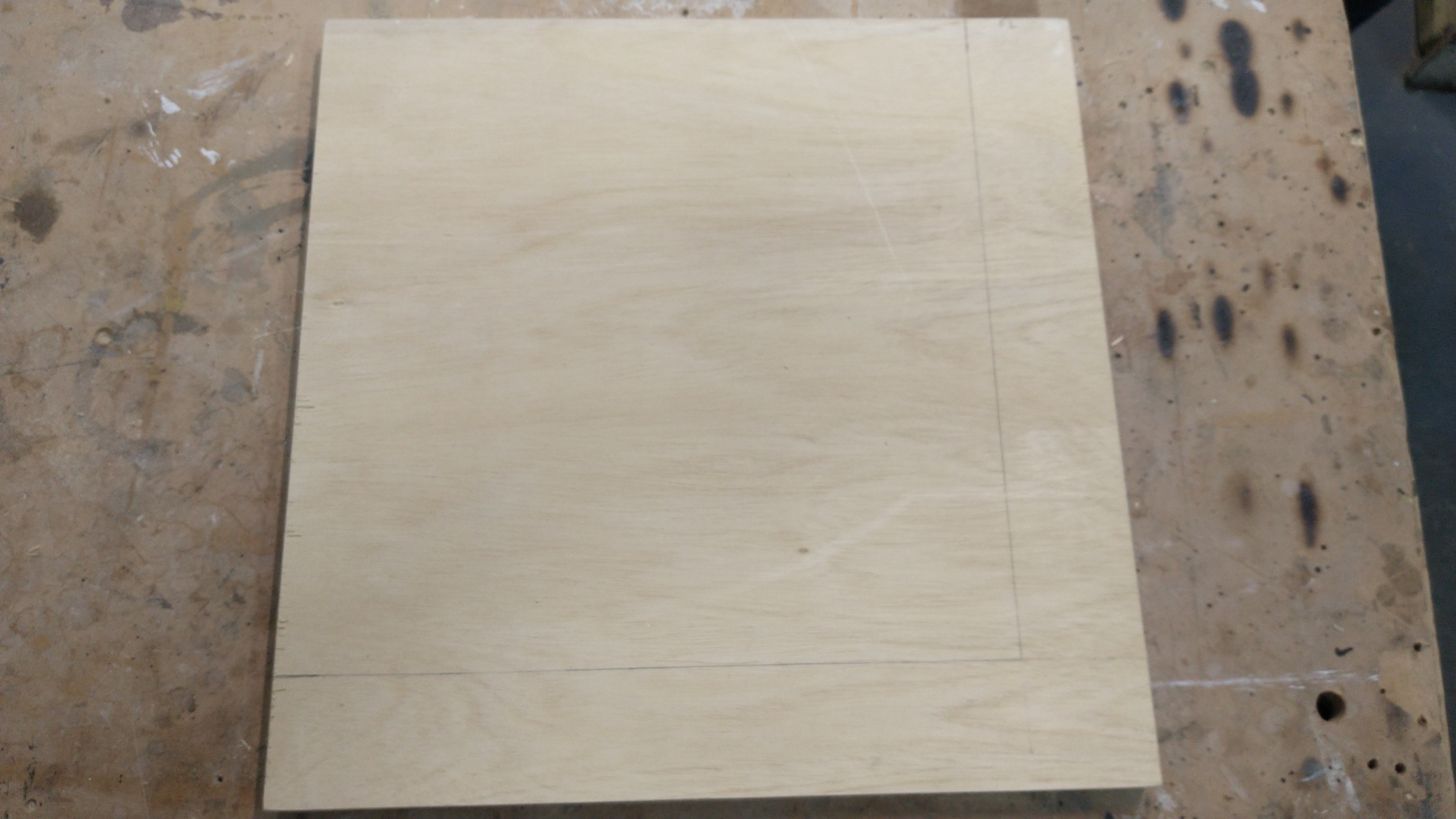
First, measure an outline for the metal, making sure to keep the correct amount of space between the metal plates, close enough together that diagonal moves will register but far enough apart that a single metal pad on the underside of the board won't be able to touch two plates simultaneously. Since the metal pads on the underside of the board are just under 4" in diameter, the metal plates should be around 4" apart.
- For each of the panels, measure
2"inward from the two inner edges, going along each edge, marking off2". - Draw a line parallel to the edge of the wood piece on each of the two inner edges. These lines mark where the metal plate should be attached.
Inset
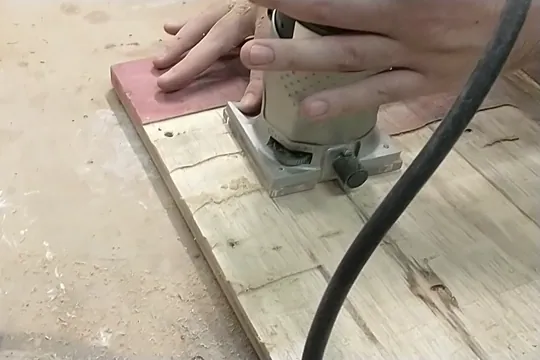
In order to get the metal plates flush with the platform, it is necessary to remove a thin layer of wood from where the metal will be attached. A router can be used to cut away a thin layer from all parts of the wood other than the cross section between the metal plates (everything other than the 2" previously measured on each piece).
- Insert a
3/4"diameter straight bit into the router. - If using 18-gauge metal plates, set the router depth to
1/16". - On each panel, route two straight channels into the wood, one along each inside part of the lines previously drawn where the metal will be set. Use a router edge guide to make a straight cut.
- Use the router to remove the rest of the wood between the channels and the edge of the wood, leaving only the cross section. In the end, there should be a recess the metal plate can be placed into on each panel.
Machine screw routing
Using machine screws and nuts to fasten the metal to the wood has a few advantages over drilling the metal directly into the wood with wood or sheet metal screws. Since machine screws and nuts can be regularly tightened, there is a better chance of them keeping the metal firmly in place throughout the lifetime of the platform, even under heavy friction. Also, if the screws ever need to be removed and reinserted or the metal needs to be replaced, the machine screws can easily use the same holes, whereas regular sheet metal screws may have trouble with the holes stripping over time.
Using machine screws requires routing which will allow washers and nuts to be used on the underside of the platform to keep the machine screws tightened in place.
Inner screws
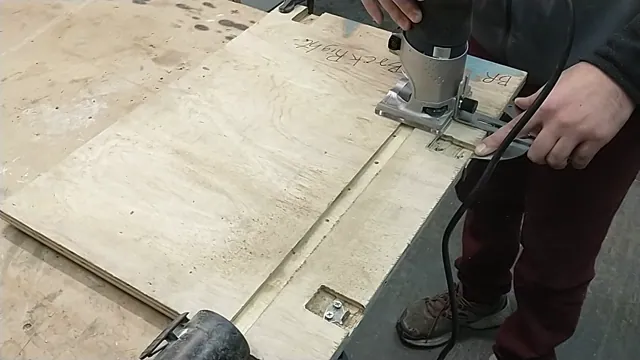
For the inner two rows of machine screws (parallel to the cross section of wood), create two 3/4" channels on the underside of each panel.
- Insert a
3/4"diameter straight bit into the router. - On each panel, using the lines already measured into the top of the panel, measure out
3/4"wide channels on the underside of the panel along the two inner edges under each metal plate. The channels should each start at the edge and come3/4"inward. The line marking the outer edge of each channel can be started by drawing a line along the side edge of the panel, connecting the top of the panel with the bottom, indicating on the bottom where the metal edges are. Draw lines from the mark straight in along the bottom of the panel to indicate where to route. - Adjust the depth of the router to
5/16". - Use the router to carve two channels with the outside of each channel along the lines drawn.
Outer screws
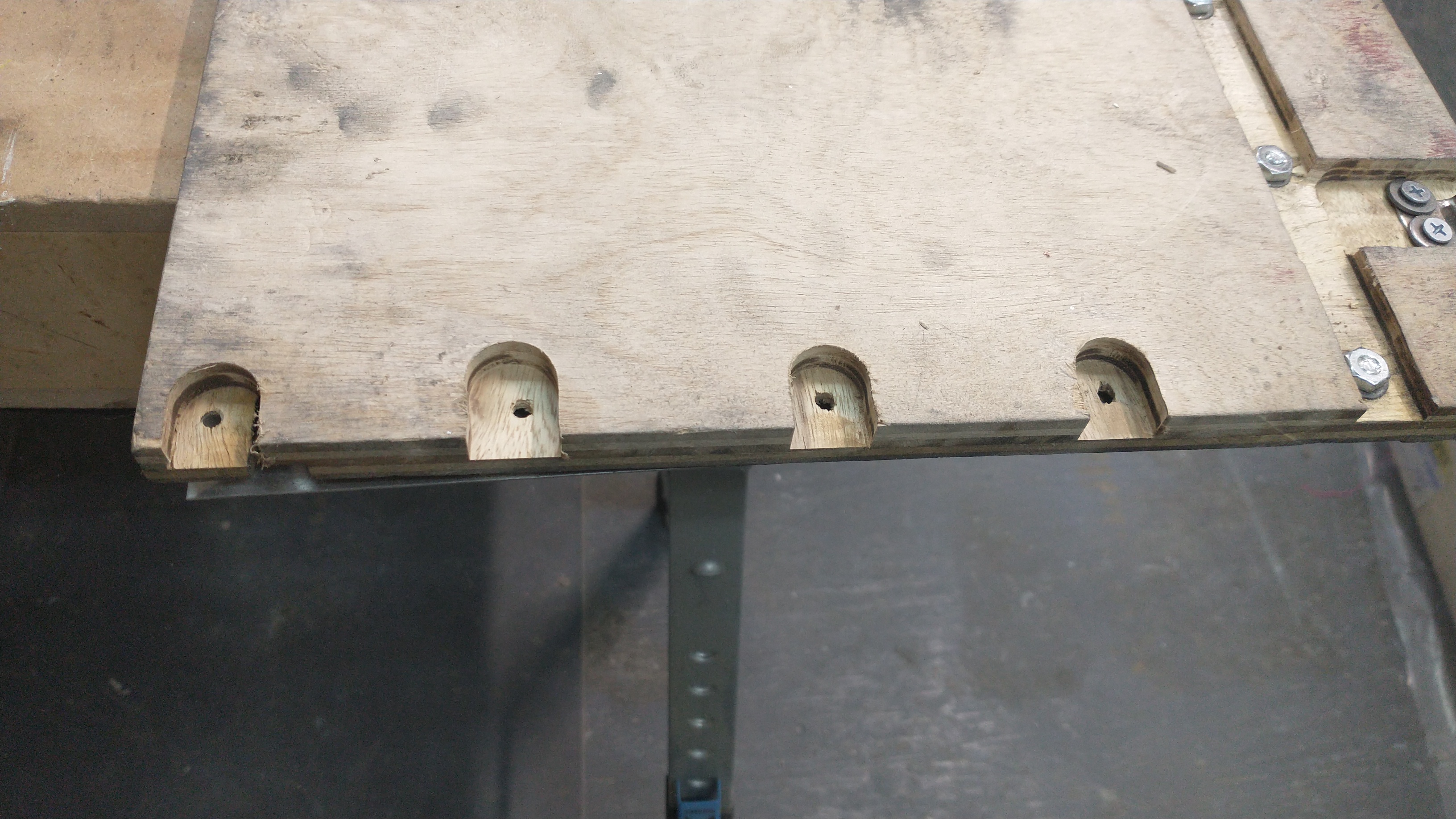
For the screws along the edge of the platform, each screw will need its own routed inset on the underside of the panel. Each screw is routed individually to avoid routing full strips of wood off the edges of the underside, which would cause the wood to crack under the player's weight.
- Measure and mark points where the screws will emerge. These points will correspond with points on the metal where the screws will be inserted. The marks should be
3/8"in from the edge of the wood and evenly spaced. Note that if the metal plates do not come up to the edge of the wood, the marks may need to be more than3/8"in. The outermost corner screw may need to be spaced differently because it would be too close to the corner to route away the wood. For the corner screw, consider moving the mark inward half the distance toward its neighboring screw along the edge corresponding to either the front or back of the platform. - Using the same router bit and depth from the previous step, route
3/4"channels in from the edge of the wood, one for each screw, each channel going in about1/2"past the screw mark to give room to the washer and nut.
Wire preparation
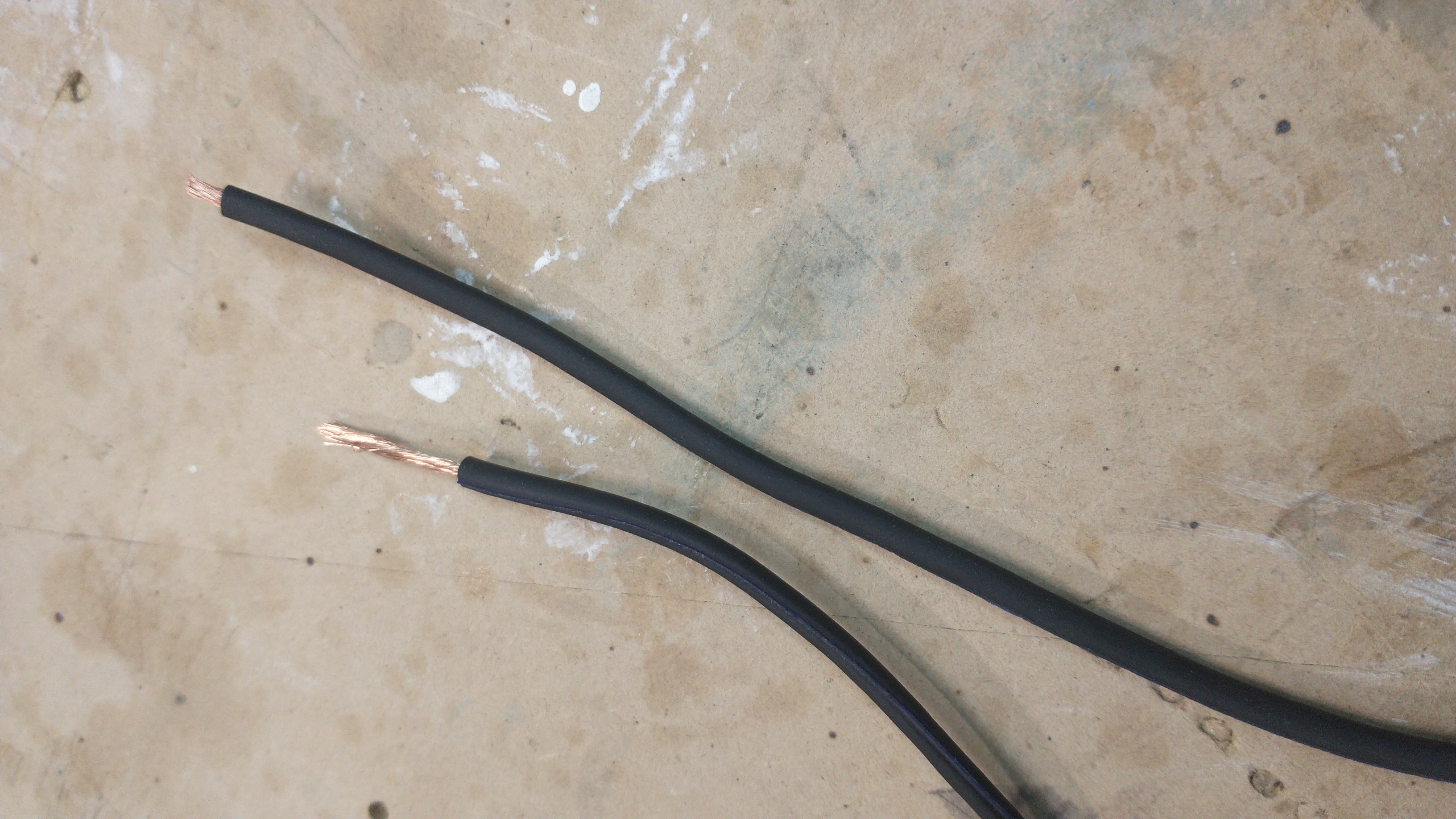
There will be four wires total, one for each metal plate. They should be cut long enough to reach the Arduino or Raspberry Pi. To have them all terminate at the same point, the back two panels should have longer wires than the front two.
- Measure the distances between the Arduino or Raspberry Pi and each metal plate. This will vary depending on the setup, and it is a good idea to measure extra distance.
- Cut wire at the measured distance for each plate.
- For each wire, at one end use wire strippers to cut off the sheathing and expose
1/4"of wire. These ends will be inserted into the screw terminals. - For each wire, at the other end, use wire strippers to cut off the sheathing and expose
2"or more of wire. These ends will be attached to the metal plates.
Metal plates and wire connections
The metal plates must be screwed into the platform, leaving the measured cross section of bare wood between them. The wires must be attached to the metal plates. To fasten the metal plates to the wood, 16 screws are used per plate, all along the edges, 3/8" inward from the edge.
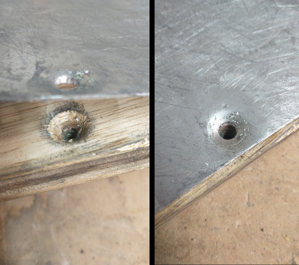
Each screw head should be flush with the metal, leaving the surface of the metal smooth even at the edges. Therefore, a countersink must be made for each screw head. Because this platform version uses thinner metal than the original, the countersink will need to be made in the wood, and the metal will be pushed into the countersink by the screw as it is tightened.
- On each panel, place the metal plate along the measured lines.
- Each of the screws should be
3/8"away from the edge of the metal. Mark points for the screws so they are evenly spaced around the edge of the metal. With one mark at each corner, there should be two marks between the corners on the short edges, and four marks between the corners on the long edge. - The outermost corner screw mark may need to be brought inward to align with the corner routing done in the previous section.
- Insert a
7/64"drill bit into the drill. Drill a hole through the metal, all the way through the wood and out the underside for each mark. Each hole should emerge in the center of its channel on the underside. - Remove the metal plate. Use either a
1/2"countersink bit or a23/64"drill bit to drill a counter sink slightly larger than the circumference of the screw head into the wood, just deep enough so that the metal will bend into the countersink after the screw is inserted and tightened from the underside. - Replace the metal plate. Insert a screw into each hole and screw it in by hand or drill it in. If the holes are not large enough, repeat step 4 with a larger drill bit.
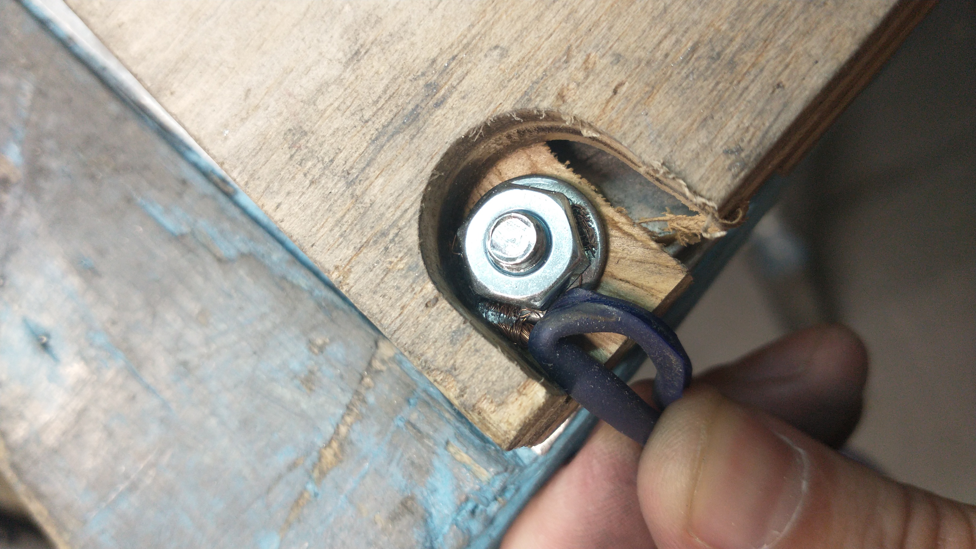
- Flip the panel over. The screws should be sticking out of the bottom of the panel. Place a washer over each screw and screw a hex nut onto the screw by hand. On the outermost corner, carefully wrap the wire around the screw before attaching the washer and nut. Holding the panel on its side, use pliers to hold each nut in place while using the drill on the top side to tighten the screw. The screw should push the metal into the wood countersink, leaving the metal surface flush.
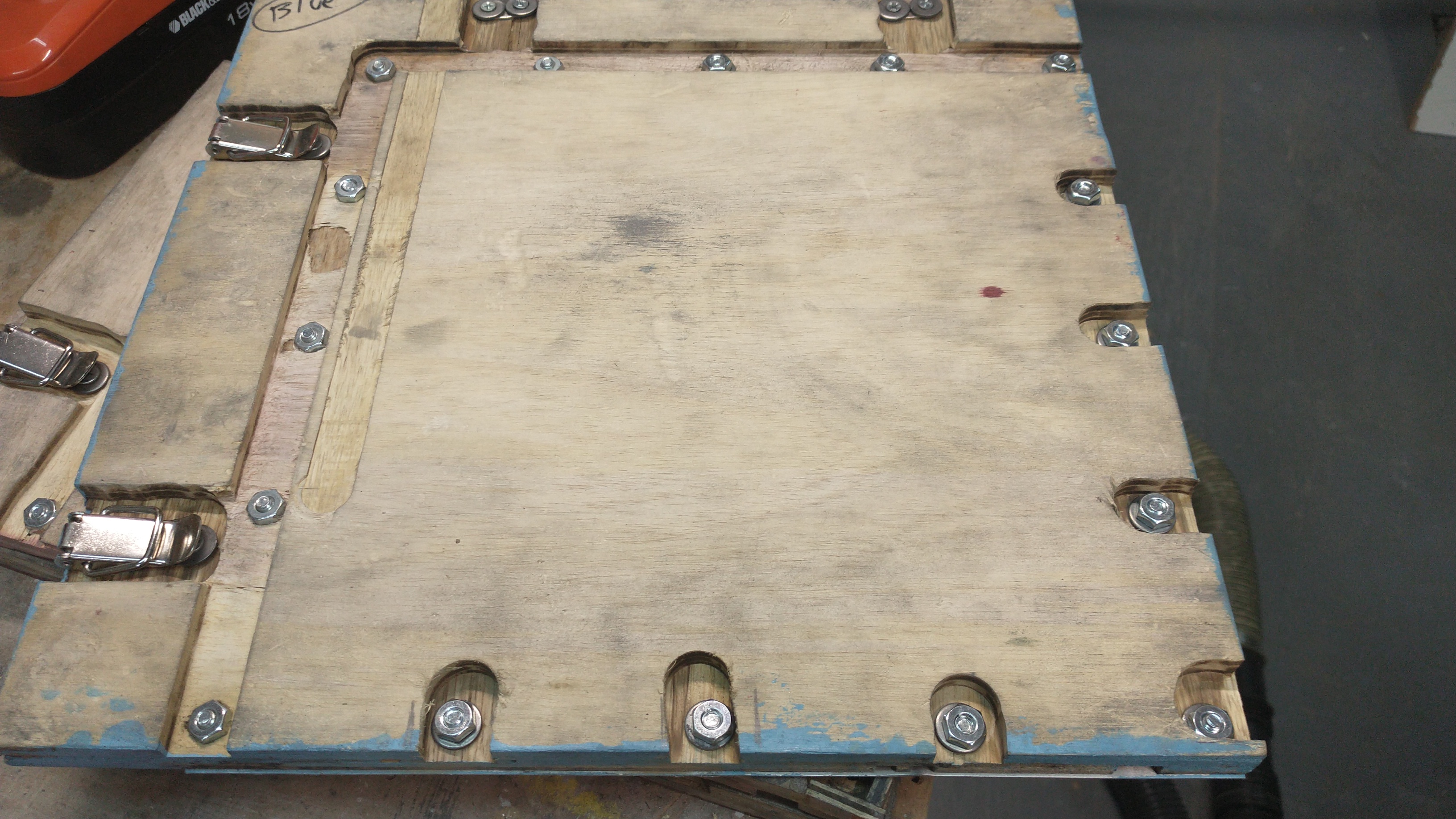
Clasps
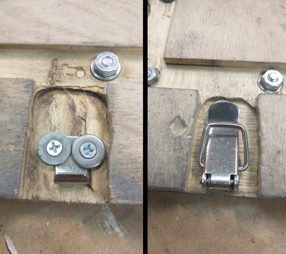
The clasps should be attached to the underside of the platform. They are necessary for holding the panels together. With 8 evenly spaced clasps, the panels will hold together firmly. Because they are fairly thick, they must be inset into the wood.
- Flip the platform on its backside, with all four panels arranged in their proper orientations.
- Along the cross section seam, place the brackets so they are evenly spaced, covering as much area as possible, without getting too close to the edge or the center.
- Trace around the bracket to mark where to route the wood. If using the clasp style brackets, leave some extra room in the outline.
- Set the router depth to
3/8". Use the router to carve a channel along the outline. After routing, put the brackets back in place. - In order to get a tight hold, the two sides of each bracket should be drilled so they are very slightly farther apart than the neutral state they come in, separated just a couple of millimeters farther apart. To do this, first draw pencil marks where the holes would be in the neutral position. Then, unclasp the bracket, and move each side back slightly, just about a millimeter.
- Drill the brackets into the wood using
#4 1/4"screws. - Clasp the brackets and ensure they are able to close and hold tightly. If not, remove the screws, adjust their positions, and drill them in again until the brackets are tight.
Non-slip padding
The non-slip padding is necessary on many surfaces to keep the platform from slipping. If the platform is placed on a very non-slippery surface like carpet, however, it may not be necessary. The padding can be placed independently under the platform, or it can be attached to the underside of the platform as described below.
- On each panel's underside, measure a large rectangular area for non-slip padding to attach.
- Cut the non-slip padding material into the shape measured.
- Apply carpet tape to the back side of the non-slip material.
- Firmly press each piece of non-slip material into its place on the underside of the panel.
Connect
The platform can now be connected to the Arduino and tested before moving on to building the board.
- Carefully and slowly flip the platform back over, taking care near the seams because the underside bracketing can make it susceptible to snapping.
- For each wire, insert its far end into its appropriate screw terminal. Going clockwise from the top left plate, the wires connect to pins 2, 3, 4, and 5.
- Use any metal conductor to touch one metal plate to another. The lizard should appear on the screen.
| ⬅ Previous Page |
|---|
| Raspberry Pi |